What if a robot could respond to changing part positions instead of following the same fixed path every cycle? That’s the advantage vision guided robotics for manufacturing can offer when sensing, decision-making and robot motion are designed around one production task.
Fixed paths can become a constraint when parts arrive in different orientations or positions. Adding a camera alone won’t solve that challenge: the system must identify the part, determine its location, communicate usable instructions to the robot and coordinate with existing controls.
This 2026 guide explains how the sensing-to-motion loop works, how to assess whether 2D or 3D vision suits the application, and which manufacturing tasks may benefit from robotic guidance. It also shows how to plan a feasibility assessment around real production conditions, including part variation, cycle requirements and PLC or SCADA coordination. Treating vision, robotics and controls as connected elements helps manufacturers assess adaptability while keeping integration complexity in view. EdNex Automation supplies and integrates robotics and industrial automation systems, including PLC and SCADA integration.
Key Takeaways
- See how vision-guided motion differs from fixed-coordinate execution when parts arrive in variable positions or orientations.
- Follow the image-to-action sequence and learn why aligning vision coordinates with the robot’s reference frame matters.
- Compare bin picking, alignment, pick-and-place, inspection and sorting to identify where vision guided robotics for manufacturing may fit.
- Build a feasibility assessment around representative parts, real operating conditions and acceptance measures set with the plant team.
- Map robot, vision, PLC and SCADA responsibilities as connected elements of a manufacturing automation architecture.
What Is Vision-Guided Robotics in Manufacturing, and What Changes on the Line?
Vision guided robotics for manufacturing uses image data to help a robot locate a workpiece and select a programmed action, rather than relying only on fixed coordinates taught in advance. This lets a cell respond to defined changes in part position or orientation without giving the robot unrestricted autonomy.
The difference matters when parts don’t arrive in precisely the same place every cycle. A fixed-path robot expects a known position. If a part shifts on a conveyor or sits at an angle in a tote, its taught movement may no longer line up with the workpiece. Vision can provide an updated target, while the robot continues to follow its programmed task logic and operating boundaries.
How vision guidance differs from fixed robot coordinates
With fixed coordinates, the robot moves to predetermined locations. This works well when parts are presented consistently, but variation may require careful positioning or changes to the setup. Vision guidance measures a part’s location from an image and uses that result to adjust the target for the task.
For example, a pick-and-place cell may be programmed to grasp a component and transfer it to an assembly station. If the component arrives rotated or slightly offset, the vision system can identify its pose and provide a corresponding target. The robot still follows defined approach, grasp and placement logic. It doesn’t independently decide what to manufacture or how to operate outside the task.
That boundary is central to a dependable design. The cell’s programmed operation and safety design should account for permitted motion, tool actions and responses to an unreadable or unexpected part.
The core components of a vision-guided robotic cell
A vision-guided cell combines sensing, interpretation, motion and coordination. The camera captures an image, and an image-processing system identifies relevant features or estimates a part’s position. That information must then be translated into a target the robot can use, with the coordinate relationship between the camera, robot and work area correctly established.
- Camera: Captures the work area and the parts presented to the cell.
- Image-processing system: Interprets image data and determines whether it has found a usable part location or pose.
- Robot and end effector: The robot moves to the instructed target, while its tool performs the planned handling operation.
- Control interface: Coordinates the exchange of status and task information among the vision system, robot and relevant cell controls.
The process is straightforward: capture an image, interpret the part, calculate a target, send the instruction and carry out the programmed action. If the system cannot identify a suitable target, its response should be defined in advance. Reliable operation depends on the complete cell, including lighting and part presentation, coordinate alignment, tooling and control integration. In automated handling cells, pairing optical systems with smart process sensors from Contrinex can also safeguard operations against feed faults and costly downtime. A camera alone cannot correct a poorly defined task or an inconsistent handoff between systems.
How the Vision-Guided Robotics Loop Turns Images into Robot Actions
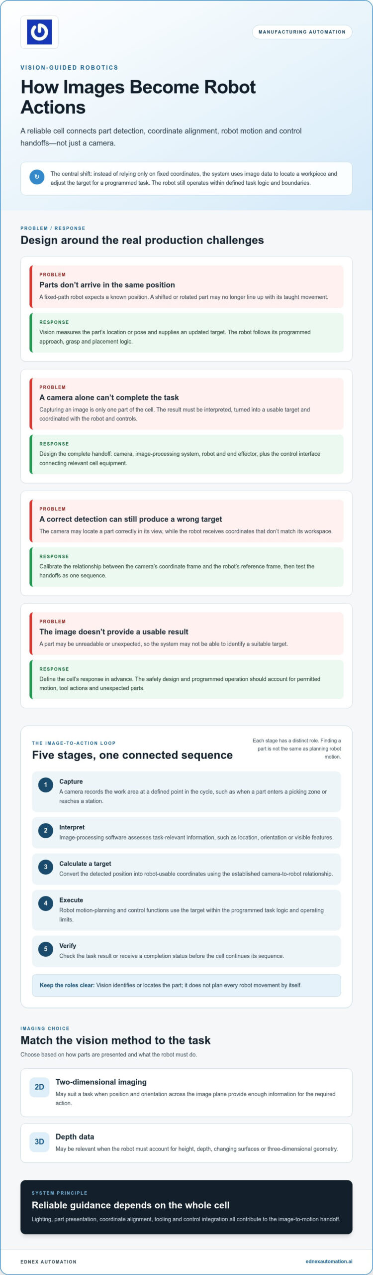
In vision guided robotics for manufacturing, image data becomes a robot instruction through a sequence of capture, interpretation, target calculation, motion execution and verification. Each stage has a distinct role: identifying a part is not the same as planning a robot path or coordinating the next machine action.
- Capture: A camera records the work area at a defined point in the cycle, such as when a part enters a picking zone or reaches a station.
- Interpret: Image-processing software assesses the image for task-relevant information, such as the part’s location, orientation or visible features. If the image doesn’t support a usable result, the cell needs a defined response.
- Calculate a target: The detected position is converted into coordinates the robot can use. This requires a known relationship between the camera’s coordinate frame and the robot’s reference frame.
- Execute: The robot’s motion-planning and control functions use the target within the programmed task logic and operating limits. The vision system identifies or locates the part; it doesn’t plan every robot movement by itself.
- Verify: The cell checks the task result or receives a completion status before continuing the sequence. The appropriate check depends on the operation and the information available from connected equipment.
A coordinate mismatch can make an otherwise clear image unusable. The system may locate a part correctly in the camera view yet send a target that doesn’t correspond to the robot’s workspace. Calibration establishes that relationship, while control integration ensures the robot receives the instruction at the right point in the cycle. Test these handoffs as a complete sequence, rather than treating them as separate setup details.
Choosing between 2D and 3D machine vision
Two-dimensional imaging may suit a task when the part’s position and orientation across the image plane provide enough information for the required action. If the robot must account for height, depth, changing surfaces or three-dimensional geometry, depth data may be relevant. Base the choice on how parts are presented and what the robot must do. Compare candidate approaches using representative parts and the required result, rather than choosing by category alone.
Calibration, lighting, and image reliability
Calibration connects camera measurements to robot coordinates, but image quality also determines whether the system can calculate a usable target. Glare can obscure edges; shadows can change visible features; overlapping parts can hide useful geometry. Inconsistent lighting or part presentation may also make production images differ from setup images. Assess these factors together: improving calibration won’t resolve an image that fails to show the features the task depends on.
Build trials around normal production variation, including actual part surfaces, orientations, surrounding equipment and lighting conditions. Record when the system identifies a usable target, when it cannot and what the cell does next. This evidence helps distinguish a sensing issue from a coordinate, motion-planning or control-handoff issue before the design moves into routine operation.
Robotics and controls need to work as a connected system. Manufacturers can consider how robotics and PLC integration fit the wider production task when shaping an automation plan.
Which Manufacturing Tasks Benefit Most from Vision-Guided Robotics?
Vision guided robotics for manufacturing is worth evaluating when variation in part position, orientation or appearance changes how a task must be performed. The practical test is whether the robot needs current visual information to complete the operation or protect quality, not whether the cell can use a newer AI capability. Compare each application against the workpiece, presentation method and required result.
| Task | Source of variation | Vision need | Validation question |
|---|---|---|---|
| Bin picking | Parts may overlap or sit at different positions and orientations. | Locate a graspable part and estimate its pose. | Can the system identify suitable picks across representative bin conditions? |
| Part alignment | Components may arrive offset or rotated before joining or processing. | Measure position so the robot can adjust its approach. | Does the measured position support the required alignment at the process point? |
| Pick-and-place | Incoming items may shift on a conveyor or fixture. | Update the pick target and, where needed, orientation. | Can the cell handle the expected presentation range and maintain its task sequence? |
| Inspection during handling | Features or defects may appear in different locations or orientations. | Present the relevant surface to inspection, or assess it during handling. | Are the required features visible and assessed at the appropriate stage? |
| Sorting | Items may vary by type, appearance or location. | Identify the relevant category and direct the item to its assigned destination. | Can the system distinguish the categories that matter under production conditions? |
Where vision guidance can address production variability
Bin picking shows both the opportunity and the limits of visual guidance. Measurements can help locate parts in varied poses, but overlap, occlusion and gripper access still determine whether a pick is feasible. For alignment or assembly, measured position can guide the robot’s approach to a component. Inspection or identification may also be combined with handling when the required features are visible and the task sequence supports it. Test each application against its own acceptance criteria.
When fixed guidance may remain the simpler choice
If parts are presented in highly repeatable positions and orientations, fixed guidance may already meet the task requirement. Compare its simplicity with the value of measuring variation. Reflective, transparent, overlapping or poorly presented parts aren’t automatic exclusions, but they are important test conditions because they can complicate image interpretation. Include the robot, tool, work area and operator interaction in the cell design. The collaborative robots in the UAE guide provides related context for workcell planning.
Prioritize candidate tasks by how often observed variation disrupts execution, the consequence of a missed or misidentified part, and whether the cell can respond safely when it cannot make a reliable decision. This task-first assessment helps separate a real production need from technology novelty.
How to Assess and Validate a Vision-Guided Robotics Application
A disciplined feasibility assessment starts with the production task, not a camera or AI capability. For vision guided robotics for manufacturing, the plant team should define what varies, what action the robot must perform and how the cell should respond when it can’t make a dependable decision. This gives the team criteria to test against operating needs instead of relying on generic accuracy or cycle-time targets.
Define the task, inputs, and acceptance criteria
Document the part types and presentation conditions the cell will encounter, including changes in position and orientation, surface appearance, and expected volume or cycle requirements. Specify the robot’s required action and the outcome that counts as success. Include normal production variation, not only the easiest parts to handle.
Before trials, agree on measurable acceptance criteria with production, engineering and controls stakeholders. Criteria may cover successful picks, correct placements, acceptable rejects, responses to unreadable images and recovery after a failed attempt. Set thresholds for the application and the plant’s requirements. No single accuracy or cycle-time figure fits every task.
- Define expected inputs: List part types, presentation changes and relevant operating conditions.
- Include edge cases: Consider occlusion, overlapping parts, glare or shadows, and changes in lighting.
- Specify exceptions: Decide how the cell handles no detection, an uncertain result, a missed pick or an unavailable downstream station.
- Agree on acceptance: Record what successful operation, rejection and recovery mean before testing begins.
Test the complete cell before scaling
Run the camera, image processing, robot, end effector and controls as one workflow. A vision result is useful only if it becomes an actionable target, the robot can perform the programmed movement and the next cell operation receives the correct status. Assess the full handoff, including what happens when a part can’t be identified or handled as expected.
During trials, record successful cycles and exceptions. Note the part and its presentation, the observed result, any robot or control response, and how the cell returned to a defined operating state. Test representative samples under production conditions, then compare the evidence with the plant team’s acceptance criteria. This helps pinpoint whether an issue lies in image interpretation, handling, motion or control coordination before the application expands.
Robot-cell validation depends on coordinated signals as well as mechanical and sensing performance. PLC and SCADA integration are important parts of planning those controls connections. To align a manufacturing task with broader robotics and controls requirements, review EdNex Automation’s robotics and controls integration services.
Integrating Vision-Guided Robotics into a Connected Manufacturing Operation
A vision-guided cell doesn’t operate in isolation. Its place in the production architecture depends on how the robot’s task, visual information and plant controls work together. For vision guided robotics for manufacturing, define which system makes each decision, what status it shares and how the wider workflow should respond when a task cannot proceed as planned.
This division of responsibility helps prevent gaps between components. The vision system can provide task-relevant location or identification information; the robot uses the resulting instruction within its programmed motion and task logic. Industrial controls coordinate the cell with upstream and downstream operations, while supervisory systems can present relevant production states when the architecture calls for it.
Coordinate robot guidance with industrial controls
Map the production sequence before specifying interfaces. Identify what allows the robot task to begin, what information or status the cell returns when it finishes, and what should happen if a part isn’t detected, a pick fails or a downstream station isn’t ready. These decisions connect sensing and movement to the production flow, rather than leaving them as a stand-alone demonstration.
Fault states, interlocks and recovery logic belong in the system design from the outset. Define which conditions prevent a task from starting, how the cell signals a fault and what must happen before operation resumes. Recovery should be deliberate and understandable to operators, not an assumed automatic response. The exact logic depends on the equipment and process, so document responsibilities across the robot, vision system and controls.
PLC and SCADA integration are part of EdNex Automation’s industrial automation capabilities. PLC responsibilities can be planned alongside the cell sequence, while SCADA can support supervisory monitoring as defined by the project. The allocation should reflect the plant’s existing controls and the information operators need.
Plan the next step around the manufacturing task
Before moving toward implementation, bring the decision framework into one concise task brief. Include:
- The task: What operation must the robot perform, and what does an acceptable result look like?
- The variation: How do part position, orientation, appearance or presentation change during production?
- The constraints: What limits apply to the work area, tooling, operating sequence and connected equipment?
- The acceptance criteria: How will the plant team assess successful operation, exceptions and recovery?
This brief gives production, engineering and controls teams a shared basis for deciding whether vision guidance addresses a real need and how it fits the wider workflow. EdNex Automation supplies and integrates robotics and industrial automation systems, including PLC and SCADA integration, as part of a broader manufacturing strategy.
To explore how robotics and controls integration can support your production requirements, review EdNex Automation’s industrial robotics solutions.
Turn a Production Challenge into a Clear Next Step
The next move isn’t to automate every source of variation at once. Select a defined operation where changing part presentation creates a clear production challenge, then bring together the people who understand the task, line constraints and desired outcome. Their shared view can help shape a project scope that is practical to evaluate and relevant to day-to-day operations.
Think beyond the initial cell as well. A well-planned automation architecture should be understandable to the teams who operate and maintain it, and fit the direction of the wider manufacturing operation. EdNex Automation provides robotics and automation integration, including collaborative robots and PLC and SCADA integration. This connected perspective helps frame vision guided robotics for manufacturing as an operational decision, not simply a camera or robot selection.
Bring your production priorities into the next planning conversation and identify where an integrated approach can support them. Explore EdNex Automation’s industrial robotics solutions.
Frequently Asked Questions
What is vision-guided robotics?
Vision-guided robotics uses image-based information to help a robot respond to a part’s observed position or features during a task. For example, a robot may adjust its pick location when components arrive slightly offset on a conveyor. The application still needs a defined task, permitted movements and a response for uncertain results. It accommodates specific production variation; it doesn’t independently decide how the factory should operate.
How does a vision-guided robot know where to pick up a part?
The system identifies a usable part location in the image, then relates that measurement to the robot’s working coordinates so it can act on the target. For a moving conveyor, the task may also need to account for when the image is captured and whether the part remains reachable at the planned pick point. The grasp itself depends on the end effector and the part’s accessible surfaces, not location data alone.
Is 3D vision always better than 2D vision for manufacturing robots?
No. The right choice depends on the information the task needs. A flat label or component presented on a stable surface may be located from image-plane position, while a task involving a part’s height or shape may require depth information. Consider the workpiece, how it is presented and the action the robot must perform. Extra dimensional data isn’t automatically useful if the production task doesn’t depend on it.
Can vision-guided robotics handle randomly oriented parts?
It can support tasks with varying part poses if the system can identify a usable target and the robot can reach and grasp it. In a bin, two parts may overlap so the visible surface doesn’t offer a safe or accessible grasp. Define what the cell should do if it can’t find an acceptable pick, such as pause for operator attention or proceed to another available part, according to the application design.
Does vision-guided robotics eliminate the need for fixtures?
Not necessarily. A fixture may hold a workpiece steady during drilling, joining or inspection, even if vision helps locate it before the operation. In another task, measured position might accommodate some variation in how parts arrive, while a simpler support still controls presentation. Compare the fixture’s role in positioning, process quality and safe access with the variation the vision-guided task is meant to address.
What can make a vision-guided robotic application unreliable?
Reliability can suffer when actual production conditions differ from those used to set up the application. Changes in a part’s surface, camera position or lighting may affect image results, while shifts in the robot or work area can affect the relationship between measured and reachable positions. Track recurring no-detection events and unsuccessful actions by condition. Patterns can help the team identify what needs adjustment or further testing.